![]()
![]()
![]()
![]()
![]()
|
|
|
TrackPlanning.com NY Signal drawn
|
First, the outline of the benchwork is drawn. The different colors in this image show how straight lines, curves and spirals can be used to design flowing benchwork edges. This was made using the standard Draw and Connect Tools in a layer not designated as a Track Layer.
Now the Connect Crooked tool is used to select the entire benchwork perimeter. Notice how you want to start the path tool at one end of an object, then select the farthest object from that end to complete the loop.
Once the Path is highlighted, select Edit / Transform / Change to Mesh to change the path objects to a single Terrain Mesh.
When you're making a non-rectangular Terrain Mesh, the program needs to clip the mesh to fit your boundary. If the first clipping results in a large number of very small edge triangles, the program will adjust the mesh dimensions very slightly and try the trim again. When it finds an alignment that minimizes unnecessary triangles in the mesh, the mesh is displayed.
The Terrain Mesh may be selected by any outside edge. This mesh was drawn in the Topography Layer, so the Layer Enable Dialog was used to change the Active Layer to the Main Track layer. The option "Allow only the Active Layer to be edited" was selected. This prevents highlighting of the mesh when the mouse crosses its boundary.
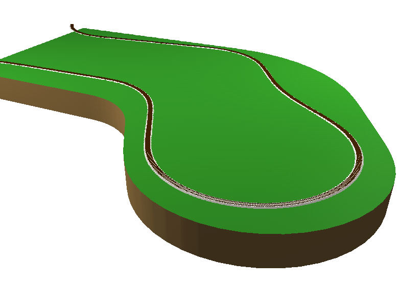
With some forethought given to the terrain you want to see, lay the track using your favorite design practices. This example shows the use of easements in all curves for a realistic look and reliable operation with its 24" radius curves.
Switching to 3D view, the automatic fascia is shown with a depth of 8 inches.
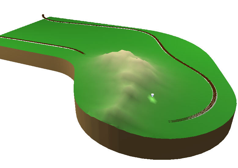
To edit a Terrain Mesh, double-click its boundary when viewing the mesh in 2D mode. The program will switch to 3D mode and present an editing marker. The marker shines onto the terrain below it to indicate where changes will be made. To move the marker, press the Left Mouse Button and move the mouse. To change the height of Terrain, hold down either the Shift key or the Ctrl key, then press and hold the Left Mouse Button. Move the mouse up and down and you will see the terrain change in response to your movements. The Shift key causes the effect to spread over its typical area, while the Ctrl key concentrates the change to a more local area. The track may become covered or raise well above the terrain - that's no problem - just design something that will look reasonable when cuts and fills are applied.
You have tremendous control over the shape of your terrain. This example was made using the Fractal Mode, with just a tiny bit of Mounded Mode. You can control the distance over which the tool has effect at any time. You can also select the colors for Color By Elevation, and where in the elevation range they have effect. You can delete or add Color Markers to make even more detailed terrain models.
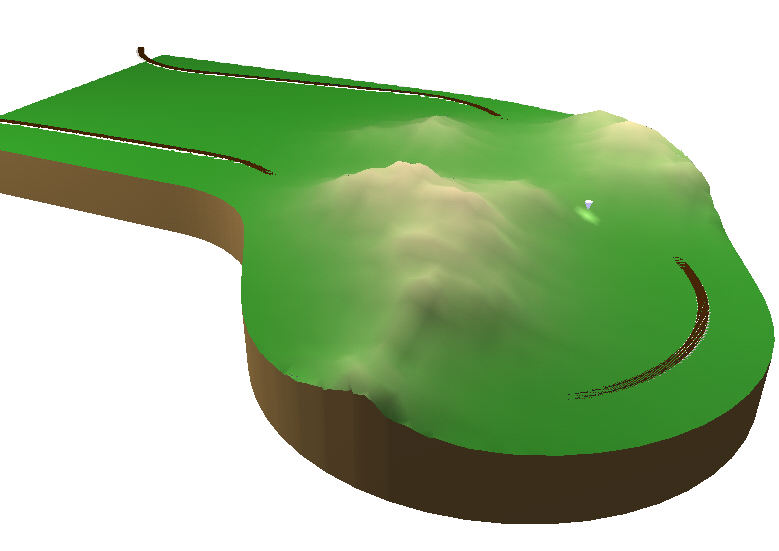
This is the final terrain design for this example. In the same way that the prototype would follow the most convenient path through hilly terrain, the terrain was designed to simulate that effect with the trackwork. However, the terrain was intentionally left "too high" so that realistic cuts would take place.
Here's the view of the terrain in 2D. The Color By Elevation has resulted in a surface from which you can clearly see the vertical characteristics of the terrain.
After selecting the Terrain Mesh, the Conform Terrain to Track command was issued. The results are already visible in the 2D view, as the terrain height is lower going through the hills.
The 3D view shows a compelling view, very much like what you'd find in the real world. That's because the cuts were made using the same kind of practices as the prototype - and you have total control over its operation! |
|
Send mail to webmaster@TrackPlanning.com with
questions or comments about this web site.
|